Is Saving Energy Really that Hard to do? Apparently it is for Some?

As many of us have been told for years, programmable thermostats are worth their weight in gold when it comes to energy savings. Well, maybe not gold these days, but you get the point. According to the Department of Energy, heating and cooling costs are one of the largest expenses associated with commercial buildings. Savings from using a programmable thermostat can be impressive. Recent studies show that proper usage of a programmable thermostat can cut business’ heating costs by approximately 25%. In the summer, such devices may shave cooling costs 15 to 25%. In fact, according to the Department of Energy, on average, every degree raised on a thermostat in the summer or lowered in the winter, saves 2% on monthly energy spend.

So why is it that so many people are now stating there is no significant savings? That’s quite simple to answer; people don’t know how to program them or just don’t bother to! According to recent information released by the EPA, “Available studies indicate no savings from programmable thermostat installation. Some studies indicate slight increased consumption.” That is quite alarming given that programmable thermostats are supposed to decrease energy usage. As it turns out, they also stated that it is not necessarily the fault of the thermostat itself, but that people don’t use the programming functions properly on their thermostats. Most, according to the study, blame difficulty in programming as the reason for not using the thermostat properly. The EPA found that nearly 90% of programmable thermostats are used like a traditional manual thermostat in which occupants raise and lower the temperatures as they feel the need to change their comfort level. This can drive utility costs much higher than needed for building owners as the temperature setting doesn’t get changed back to a normal setting when people leave the building.

As BAS contractors and HVAC specialists, we certainly know that using a programmable thermostat saves energy. As shown above, it is very expensive to leave the temperature inside an office building constant day and night through the use of a manually operated thermostat. Programmable thermostats allow business owners to make adjustments for energy savings automatically.

So how do we change this trend? The best solution for now is to share the facts and educate your customer. Explain the overall benefits to them, but most importantly don’t just program their thermostat for them and walk away. Make them program it while you’re there and you can walk them through it. Not only does this give them peace of mind, it assures them that you understand the benefits and are looking out for their best interests.

Here are some basic tips you can share with your customers when showing them their newly installed thermostat:

  • When programming the thermostat, keep it set at a constant temperature for long periods of time, such as 12 to 14 hours when the space is not occupied.
  • When closed for a longer period of time such as holidays, set the hold button at a constant temperature. Or, with many of the new programmable thermostats you can set a holiday schedule.
  • Resist the urge to override the settings. Every time that is done it costs money. Installing thermostat guards can help prevent this as well.
  • If you have zoned heating and cooling, install a programmable thermostat in each zone. Especially if you have areas that are not occupied for long periods of time.
  • If your thermostat runs on batteries, change them at least once a year.

As we move into the next decade we face even more challenges when it comes to building automation and energy savings. Wireless technology is upon us and it is making a huge splash in the HVAC industry. Programmable thermostats are no stranger to this shift in technology as there are now many wireless options available. Also, the never ending trend of personalized control from smart phones and remote programming options has become part of most thermostat manufacturer’s standard portfolios. Kele has many of these in our offering and we can help with them as well.

All in all, the trend for most customers when it comes to programming thermostats and planning for energy savings is quite simple…make it simple and make it automated and they’ll follow those plans and guidelines. Well, the manufacturers’ are doing their part by making it automated. It’s up to us to continue to educate everyone to make it simple.

Green Buildings need Clean Electrical Power for Sustainability

Major changes are taking place in the United States as we all move forward to reduced energy consumption and utilization of renewable energy sources in our homes, offices, campus environments, and factories.

As new technology becomes available with ever increasing returns on investment many owners are ready to become part of the “Green Movement” that is currently taking place all across america. No question about it the time is right for all us to move forward with our Green initiatives.

With this in mind it is important to understand the goal here is to save money across all of our operating budgets. The two basic tenets of a green operation are energy efficiency and sustainability. In order for a building, process or product to be truly “green” it must achieve both of these goals.

There are many products and services available today that can dramatically reduce our consumption, improve our efficiencies, and supplement our energy sources. These new technologies VFDs, LED lighting, Building automation Systems, Solar generation, Battery Storage, to name a few all have one thing in common, they affect the the power distribution in our building in many ways. Many times it is a combination of these building changes that begin to interact with each other.

For example, having re-lamped an entire garage with LED lighting retrofits a hospital was pleased with the energy savings they were enjoying until they had failures of the lights due to to power quality issues in the building during generator operations. All of the energy savings were lost due to the cost of replacement electronics.

Sustainability of the equipment in our buildings is highly dependent on the Power Quality within our buildings. Many repairs or glitches within our systems can be traced back to power quality issues when adequate Power Quality Monitoring is done.

In the past it has been an expensive time consuming effort to have power quality surveys done in the buildings. Most cases these were done after the fact when problems had already caused major disruptions and equipment failures. This reactive method of understanding the Power Quality Dynamics of our building may have gotten us by years ago, but with all of the new changes taking place a more proactive real time Power Quality Monitoring Solution is needed.

The ability to install powerful “Real Time” Power Quality Meters with alarming functions and data collection is now highly cost effective and key to maintaining sustainability of our buildings. These PQUBE Power Quality meters are like the Black box recorder on an aircraft. They sit within the electrical cabinets and switchgear monitoring Power Quality 24/7 in real time.

Once an event is detected they generate alarms and reports as to what the event was, how long it lasted and most important they identify their location which is critical in understanding our buildings operations.

Taking only 30 min to install, and no software to learn the PQubes are the most cost effective and useable Power Quality Meters to date. Their small footprint (about the size of your hand) allow them to be retrofitted into existing electrical panels, transfer switches, and switchboards at many locations within your building.

As we make these major investments in green technologies it only makes sense that we know our buildings Power Quality, real time, all the time. PQube Power Quality meters put you ahead of problems before they become disasters.

Kele Services

Often times when people think of Kele they think of our huge product selection and availability. It’s true—not only does Kele provide nearly 60,000 products to choose from, we also have unlimited access to hundreds of thousands of product SKUs from over 300 of the industry’s premier manufacturers. But did you know that Kele has several services that could help drastically simplify your projects and workload? Here are some of our most used services:

1. Custom Panel Fabrication

Kele has been building custom panels for over 30 years and is an expert in panel layout, specification and assembly. We are here to help with your panel fabrication needs by providing parts for enclosures/panels from our $10 MILLION INVENTORY. Not only do we have the inventory to support your custom panel needs, we also thoroughly review all panel designs, perform quality control testing on every panel and have a short lead time. We stay flexible and our panel assembly team builds quality, tested panels to meet YOUR DEADLINE.

2. Custom Valve and Actuator Assembly

Kele’s Production Shop removes the guesswork from tedious product assembly. Most orders are assembled and shipped the same day—a free service to you from Kele. We offer the largest selection of valve and actuator brands in the business. In our custom valve assembly shop we can get your electric or pneumatic actuators professionally installed on our wide variety of 1/2″ to 6″ ball, zone, and globe valves. We also provide free tagging for easy identification when they arrive at your jobsite.

When it comes to customized assemblies, Kele also offers a wide selection of pressure transmitter assemblies with bypass valves, gauges and enclosures for protection during startup and maintenance, as well as protection against the environment. We also offer a variety of light assemblies for controls components, indicators, and labeling to make your peripheral components installation and maintenance easy.

3. Custom Calibration Solutions

At Kele, we use precision calibration equipment to set your specified signal ranges and engineering units. Most orders are calibrated and shipped the same day. Calibrated products include: differential pressure transmitters, temperature transmitters, output transducers, flow transmitters, power supplies, isolators, lighting contactor initiators and much more. Need help connecting your calibrated devices to the automation system—no problem. Our technical support team is available for any troubleshooting needs you may have.

4. Technical Experience

The whole idea of Kele started with the unique needs of BAS engineers and contractors in mind—an idea that has grown into 30 years of outstanding customer service and unmatched technical support. In fact, our client-facing, technical team has a total of 350 years combined experience.

One Source Solution

Kele’s entire business model is founded on the concept of providing a ‶one-stop solution”—where not only can you get EVERYTHING YOU NEED FROM ONE SUPPLIER, but have it shipped to you quickly and know that you have the technical support when you need it most. That’s why we not only provide our customers with the best product selection and availability in the industry, but we also offer several valuable services to help our customers simplify and streamline their projects.

For more information on the services Kele provides, please visit us on Kele.com or call 1-877-826-9045.

Coming Soon—New Kele.com & 2014-15 Kele Catalog

At Kele—we’re committed to providing you the best products, services and solutions in the building automation and HVAC/R industries. And we’re starting 2014 off with two new solutions that will help you get the job done right! In the first quarter we will be launching a new Kele.com and will be releasing our 2014-15 Kele catalog.

New Kele.com:
Fresh, sleek and easy-to-use are just some of the things people are saying to describe the new Kele.com. But we didn’t just update the look and feel of the site—once the site launches you’ll also find:
• New product landing pages and search functions to help you find the products you’re looking for faster,
• New product recommendations based on what you’re shopping for,
• A new video library to help stay ahead of the game,
• An enhanced cart and checkout process,
• And new line card and link shortcuts for quicker site navigation.

And don’t forget—online orders of $750 or more qualify for FREE SHIPPING!* So be on the lookout for the new Kele.com—you’ll be glad you did!

New 2014-15 Kele Catalog:
We may be biased, but the new 2014-15 Kele catalog is our best yet. When it comes to catalogs, Kele sets the industry standard. With this new catalog you’ll get:
• Information on 965 product families including 206 new product families,
• Easy-to-find wiring diagrams, dimensions and everything you need to spec a product,
• Valuable information on Kele’s services: in-house custom panel fabrication, custom valve and actuator assembly, custom calibrations, kitting and tagging,
• As well as valuable information on how Kele is your one-stop source for all of your building automation and HVAC/R needs.

The catalog should be ready to ship sometime in March 2014. Click here to request your new 2014-15 catalog today.


*Eligible in the 48 contiguous U.S. state only. Qualified customers only.

When the Controls Just Won’t Work

I have an old engineer friend I’ll call Bucky (not his real name). Bucky was burned years ago when he designed an HVAC system that turned out to have insufficient capacity to keep the building comfortable in winter. In fact, the perimeter offices were in the low 50s (°F) (low teens °C) when the first cold snap hit. When I say he was burned, I mean it figuratively – but the occupants of the building were thinking about burning him literally.

Well, old Bucky was not going to be burned again. We joke that the architect has to specify stronger door hardware when Bucky is doing the mechanical design, so that the doors don’t blow off the hinges from his absurd supply air quantities.

This leads to a control problem on Bucky-designed jobs. I had to install and program a building automation system for a Bucky job, and it wasn’t a good experience. How can one tune an office temperature control loop when the reheat box can warm the room faster than the temperature sensor can respond? The occupants would essentially be subjected to supply air temperature, which could reach 130°F (54°C) in heating mode.

I first went with my tried-and-true PID tuning method that I learned from a DuPont instrument engineer in the early 1980s. This method had never failed me until I tried it on Bucky’s HVAC system. I worked for a couple of hours on a single office but I could not get anything near stable control. I tried adding a feedforward loop to give the PID loop advance notice that the oversized hot water valve was about to open. That took programming time and it didn’t help at all.

So I went back to the office and batted the problem around with a group of my peers. We discussed, we calculated, we got out our controls books. We came to no good conclusion.

The next day, I programmed all of the interior spaces with no problem. There was way too much air but my tuning method resulted in stable control on the first pass. Then I went to ponder the perimeter offices again. As the building was approaching occupancy time, the painters were gone and the carpets were being installed. There happened to be a carpet layer in the office I went to first. I thought out loud for a minute, then I vented to him about what a pain the air system was for me. He sat up on his heels and listened, then said, “Seems to me there ought to be a way to reduce the air and water flows.”

I turned mighty red with embarrassment at that time. I thanked the carpet layer and went to call the test and balance fellows. They agreed to cut back on the water and air to the perimeter spaces if I could convince Bucky that I needed it. Well, Bucky came to the job site and it was pretty easy to convince him by getting him to stand in a perimeter office for a while. Problem solved, but not by me. They say that if your only tool is a hammer, then every problem looks like a nail. That was my problem in a nutshell. I was a controls guy, so I focused only on the controls.

The lessons I learned were: 1) Engineers can be wrong (yes, really!); 2) When a system can’t be tuned, the system might need fixing; and, 3) When all else fails, ask the carpet guy.

THE (RS-485 Network) TERMINATOR Or The Dance of the Data Pulses

If you’re involved with building automation systems you know (unless you’ve been living under a rock like the guy in that insurance commercial) that the modern trend is to connect all your building controls together on networks. Networks make it easy to add or move control nodes as your building control needs change since the nodes all connect to the network in a consistent, simple manner.

Obviously the various monitoring and control nodes on a building automation network must be able to talk to each other over some sort of medium. Both wired and wireless networks (or a hybrid combination of the two) are possible. Almost all wired networks deployed for building automation use twisted-pair communications cables. There are three popular types of twisted-pair communication schemes in use:

RS-485 (BACnet MSTP, Modbus RTU, Metasys N2 protocols)
FT-10 Free Topology  (Lontalk protocol)
Ethernet (BACnet IP, Modbus TCP protocols)


Today we are going to discuss the RS-485 twisted pair communications scheme and the significance of a little component called the “network termination resistor.”

A twisted-pair communications cable, as the name implies, has two insulated signal conductors twisted around and around each other at a consistent (N turns per inch) twist rate. Twisting the insulated conductors around each other reduces noise radiating outward and also improves immunity to external noise pickup. Twisted pairs are especially beneficial when used with a certain type of transmitter and receiver hardware known as “differential” signaling hardware which is used in RS-485 communications.

Twisted-pair communications cables have an electrical property called “characteristic impedance.” A cable’s characteristic impedance could be simply described as “how the cable looks to a high speed data pulse traveling down the cable” without getting into a lot of electromagnetic theory.

A cable’s characteristic impedance is expressed in units called “ohms.” You don’t need to worry about what an ohm is for purposes of this article.

Those of you who have some electrical experience are thinking that maybe you can measure the characteristic impedance of a cable by attaching your DC ohmmeter to the conductors and taking a reading. Sorry, it won’t work! You’ll just measure infinite resistance or pretty close to it. A cable “looks different” to a high speed data pulse than it does to a steady state DC voltage applied to it.

Sometimes a data cable will have its characteristic impedance stamped on the cable jacket, sometimes not. Most twisted-pair data cables will have an impedance somewhere between 100 and 150 ohms. A data cable specifically marked for RS-485 applications will have a characteristic impedance fairly close to 120 ohms.

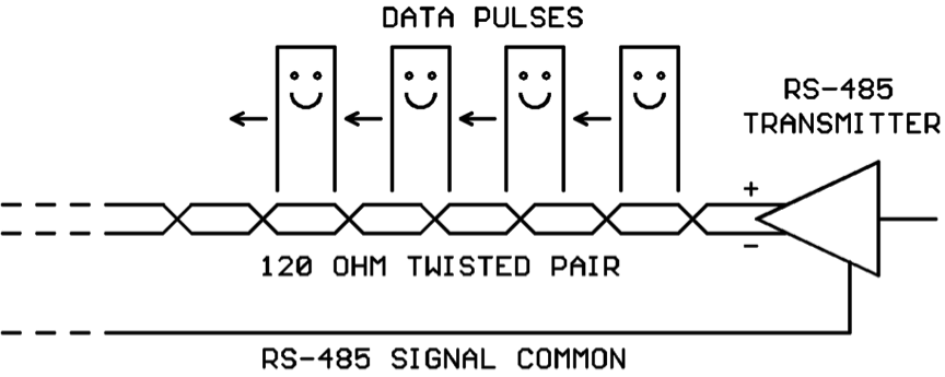
Now as a data pulse travels down a twisted-pair data cable, you might say it “gets used to” the cable’s characteristic impedance. As long as the cable’s impedance doesn’t change unexpectedly the data pulses happily propagate along:

*** RS-485 WIRING TIP #1:

RS-485 will sometimes work with only the twisted pair connected between nodes, but you have a much better chance of making it work reliably if you also run the RS-485 Signal Common wire between the nodes. This topic really deserves its own tech article and we aren’t going to delve into it any deeper today! Just remember to provide the signal common hookup whenever possible.

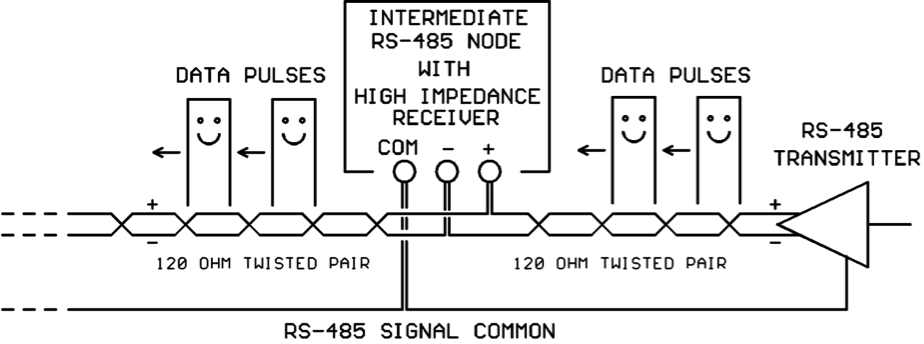
Now RS-485 architecture allows many nodes to co-exist on a communications cable. So the transmitted data pulses will be read by all attached nodes. To keep from loading the transmitter too heavily, each RS-485 receiver has a high-impedance (12000-96000 ohm) input.

At each intermediate node (nodes not connected at the ends of the cable), the data pulses arrive on a 120 ohm twisted pair and leave on a 120 ohm twisted pair. The high impedance receiver inside the node does not load down the line, and so the data pulses happily travel on to the next node on the line:

*** RS-485 WIRING TIP #2:

For intermediate nodes on an RS-485 line, DO NOT make “stubs” that “tee” into the main twisted-pair trunk line! Run the incoming pair and the outgoing pair directly to the screws on the intermediate node as shown above.

So our data pulses are happily traveling down the twisted-pair communications cable being read by each intermediate node on the line until they come “to the end of the line” (cue ominous background music!).

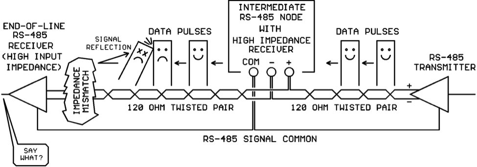
At the end of the line, the data pulses traveling on the 120 ohm twisted pair suddenly encounter the high-impedance input of the last receiver on the line. This is known in transmission-line theory as “impedance mismatch” and it isn’t good!

When the data pulses hit the impedance mismatch at the end of the twisted pair, some of the energy in the pulses is literally reflected backwards up the line where it collides with the other data pulses. If the energy reflections are bad enough, the RS-485 receiver may not be able to interpret the data pulses correctly:

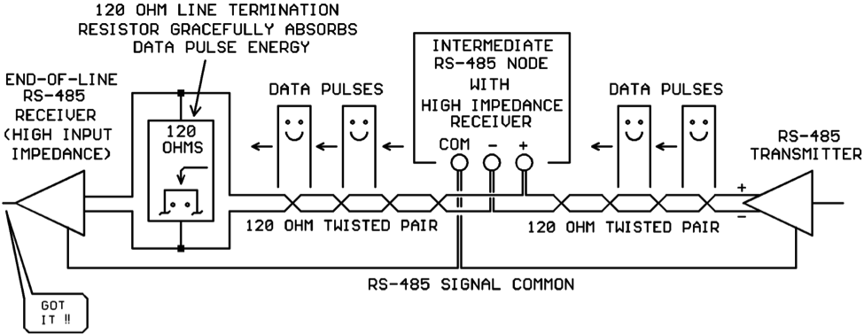
Obviously we’re going to have to do something about the impedance mismatch at the end of the line!  Fortunately, there is an inexpensive fix for this.  A small electrical component (a 120 ohm resistor) can be purchased and wired across the ends of the twisted pair.  Then, when the data pulses get to the end of the line they continue to see an impedance of 120 ohms due to the presence of the resistor.  Instead of reflecting, the energy travels into the 120 ohm resistor where it is converted into miniscule amounts of heat, and the data pulses fade away gracefully:

The 120 ohm resistors are inexpensive and easily obtained from distributors.

*** RS-485 WIRING TIP #3:

Only place 120 ohm termination resistors at the ENDS of the RS-485 twisted-pair cable.  Do not install termination resistors at any of the intermediate RS-485 nodes:


Conclusions

120 ohm network termination resistors placed at the ends of an RS-485 twisted-pair communications line help to eliminate data pulse signal reflections that can corrupt the data on the line.

We have heard anecdotal stories about how adding termination resistors did not help, and in some cases made matters worse!  That’s always possible, real-world network installations don’t always follow the assumptions made for a “typical” installation.  But on the whole the termination resistors will help network performance more often than they will hurt it.

Remember, network termination resistors are yet another tool in your network installation/troubleshooting toolkit.  They are not a cure-all for all network problems.  Keep a bag handy, and use them when it helps!


Kele Celebrates 30 Years!

Dear Valued Customer,

I would like to take this opportunity to thank you for your business. This year we celebrate 30 years servicing the needs of the building automation products industry and we take great pride in our achievements by offering a wide selection of products from almost 300 manufacturers.

30 years ago Kele’s founders Roger Johnson and Ronnie Randall identified several problems with purchasing products in the HVAC/Building Automation Industry.  They were BAS/Mechanical contractors at the time and were frustrated because they had to go to so many different suppliers to get the parts they needed.  In addition, getting technical advice on a timely basis was challenging at best and the timely delivery of those products was time-consuming and inconsistent. With the need to simplify product sourcing, offer outstanding customer service and provide quality technical support, Kele was born.

The concept was simple and continues to this day, distribute high quality products from our large in-stock inventory, ship that day if needed and provide expert technical support all under one roof.  From our location near Memphis, TN, home of FedEx and one of UPS’s largest shipping hubs in the country allows Kele to provide fast reliable delivery throughout the United States and to over 60 countries around the world.

In 2013, Kele continues refining the past 30 years of experience to continually improve on that concept.  Our technical support team has over 350 years of industry experience. Our dedicated sales teams provide valuable support to all of Kele’s customers. Our product and information packed website Kele.com is open 24/7, 365. Our massive $10 million inventory is comprised of the best selection of top quality products. Kele continues to be your one stop shop for products, solutions, custom panels, simplifying everything from your order to quick delivery and unmatched technical support.

We want to thank you for helping us reach this milestone because we could not have done it without you!  We appreciate your business and loyalty to Kele and look forward to serving you for the next 30 years and beyond.

Sincerely,

Tim Vargo
CEO, Kele, Inc.

Humidity Sensors in Distress

Let’s start with a riddle:

Q: They’re dirty, they’re annoying, they cause all sorts of trouble, they make everyone uncomfortable, and they’re hard as heck to catch; but, they’re not the pesky flies that buzz around one’s picnic potato salad? What are they?

A: Humidity sensors abused by hostile environments.

You’d be surprised where we find hostile environments. They’re not always in industrial plants and oil fields. At one point, the office in which I sit was a hostile location. On occasion, it still is. Read on.

Condensation

Believe it or not, humidity can be hostile to a humidity sensor. That is, humidity is hostile when the moisture in the air is allowed to condense into liquid water on the surface of the sensor or its electronics.

Any time an object’s surface temperature is below the dew point of the surrounding air, condensation will form on the object. If the object is exactly at the dew point or just a degree or so below it, a fine mist will form all over it. If the object is much colder, say 10°F (5.6°C) or more below the air’s dew point, a fully wet surface and active dripping will be the case. To prove the latter case to yourself, take a frosty cold can of your favorite soda outside on a muggy summer day and observe the puddle wherever you set it down.

So how is this hostile to a humidity sensor? After all, being wet is just the same as 100 percent relative humidity, right? Wrong. When we say 100 percent relative humidity, we mean that the air is holding all of the water vapor it can hold at a given dry-bulb temperature. We use the term saturated air for this condition, and it is a special point at which the air’s dry bulb temperature is equal to its dew point temperature. Humidity sensors handle that just fine. Saturated air does not necessarily mean that the surfaces of things are wet. In fact, is unlikely that a humidity sensor or its electronic parts are wet because they each dissipate a little bit of power; this power warms them, so their temperatures should be a little bit higher than the surrounding air; their surfaces should be above the dew point temperature, so they should stay dry.

When a sensor gets wet, it will typically give a 100 percent humidity output. But it takes a while for it to dry out even after the surface condensation evaporates. Think of a humidity sensor as a tiny sponge. The liquid water that it has soaked up will take time to wick to the surface and evaporate even if drying conditions are good. If drying conditions are poor (high humidity), the time can be very long. Some sensors dry more quickly than others, but they all take time.

When the sensor finally gets dry, it has a new component to it. While water condensed from the air is pretty clean, it’s not perfectly pure. It leaves some residue on the surface from which it evaporated. One bit, or even a dozen, may not affect the accuracy of the sensor. Regularly repeated exposure to liquid will make those tiny bits of residue add up to a coating around the sensor that can seriously shift its calibration.

So what makes them wet, then?

Unusual conditions can cause a humidity sensor and its electronics to be colder than the dew point of the surrounding air, and there are also conditions in which other objects above the sensor get cold and drip condensation down on it. Here is an example, along with the solution that was employed to get proper humidity sensing back on track.

The Sensor is Blowin’ in the Wind…

The most prevalent occurrence of condensation indoors is when the humidity sensor lies within a room’s supply air stream during summer months in humid climates. One example came from a specialty retail store that required pretty good humidity control in its showroom. The store is located in a city with consistently humid outdoor air. Sorry, the names of the store and city are omitted to protect the innocent.

This store had supply air diffusers designed to discharge air across the ceiling at enough velocity that it did not fall until it reached the wall. Thus, anything mounted on the wall at the falling point can be considered to be sort-of in the supply air stream. That’s where this store’s humidity sensor was mounted. Unfortunately, it was also mounted fairly close to the store’s front door. On warm, humid days, the outdoor air would swoosh in when a customer opened the door. Also unfortunate was that the humidity sensor was directly in the path of that swoosh of warm, humid air. So, the sensor would be nice and chilly and then get hit with a blast of air with a dew point much higher than the sensor. This collision of warm humid air with the chilled sensor created instant wetness. Worse, it went on all day long, every day.

Not only did this poor sensor read 100 percent most of the time in the summer, it also was toast after only six weeks in place. When it was opened, it was obvious what had happened. The sensor element and all of the electronics were covered in a fine layer of dust. The contractor relocated the sensor toward the middle of the store, out of the way of any supply air and out of the way of the incoming air from the front door. The sensor then gave proper, accurate readings instead of bouncing up to 100 percent all day. It also lived happily ever after. It’s two years old at the time of this writing.

Corrosives and Other Nasties

The bulk of this article is about condensation because it seems to be the least understood of the humidity sensor enemies. Corrosives and other foreign substances (volatile organic compounds or VOCs) are more obvious destroyers, but some of them have sources that are not so obvious.

Silicones are the most surprising hostile substances for humidity sensors in general. Many instances have been reported in which silicone sealant has been used to caulk around an installed outdoor air humidity sensor’s wiring box or conduit body. A few indoor sensors to our knowledge have been attacked by the use of silicone sealant behind the sensor to insulate it from the wall cavity. One trouble with silicone sealants is that they emit the volatile part of the goop as it cures. The volatile part is typically a hydrocarbon solvent – not good for the innards of a sensor element. These vapors can shift the sensor’s calibration a bit. Repeated exposure can shift the calibration a lot. Another trouble is that uncured silicone sealant itself can spread rapidly over surfaces both by wicking and through air. This substance can shift the calibration of a humidity sensor by 2 percent to as much as 10 percent. If a sensor must be installed with the use of silicone sealant, wait until the silicone cures before installing the sensor. Even better would be to use an alternative like latex caulk.

Corrosives are harder to deal with. Some commonly encountered sources of corrosives include swimming pools, paints, paint strippers, solvents, wood preservatives, aerosol sprays, cleansers and disinfectants, moth repellents, air fresheners, stored fuels, automotive products, hobby supplies, dry-cleaned clothing, and personal care products. All of these things emit volatile organic compounds (VOCs) that are not friendly to humidity sensors and their electronics. As the term corrosives implies, these particular VOCs eat away at the sensing element and uncoated parts of their electronics.

When corrosives attack on a regular basis, the sensor will usually shift calibration slowly until it suddenly dies completely. A corrosion-resistant sensor can weather the attack and prolong the time between replacements. Some (very expensive) sensors are nearly immune to such corrosion and are typically found in industrial or laboratory environments.

Other Stuff can treat humidity sensors badly. For instance, plain old dust is very common. The effect of a routinely dusty environment will be a delayed response time that worsens as the dust gradually coats the sensing element. After totally enclosing the element or filling the elements filter, the output of the sensor’s response time will be so long as to present a steady output to the reading device or controller. One solution for dust is to place the sensor in an aspirated box with a washable or changeable filter.

Notes on Filtering: Some humidity sensors include a gas-permeable filter such as Gore-Tex® that does not allow passage of liquids or solids. That can be a big help in keeping the bad things away from the sensing element. It won’t stop condensation that occurs inside it from humid air, and it won’t stop corrosive gases. It will keep the sensor safe from dust, drips, and rain. The filter might require occasional cleaning, though. Sintered metal filters do a good job with particulate matter and an OK (but not perfect) job with dripping water or rain. They, too, may require occasional cleaning in dusty environments.

So how did my office become hostile to a humidity sensor?  Let’s just say it involved a hot plate, some Indian food (chicken tikka masala), an office neighbor with a sensitive nose, and two cans of Lysol spray.  I’ll leave the rest up to your imagination.  My humidity sensor was a gone…

Conclusion

Ways can almost always be found to mitigate the effects of condensation, corrosives, and other nasties in the air that attack humidity sensors. The tough part is knowing what they are in advance. The easy part is calling Kele Technical Support at 877-826-9045 for assistance in winning your sensor’s battle against these elements.

What Are Power System VARs?

Most people involved in building automation are familiar with kW, which is the rate at which a building is consuming energy from the power company. But there is another power system parameter known as VAR/kVAR which is less well understood. In this article we will attempt to dispel some of the VAR mystery.

The term “VAR” stands for “Volt-Amperes Reactive.” Guess we’re done here, right? What’s that? You were hoping for a little more explanation. OK, let’s dig a little deeper.

First, for any readers that are complete newbies to power monitoring, let’s explain the ‘k’ prefix frequently found on power system readings. “k” simply means “times 1000.” So three kV is three thousand volts, two kW is two thousand watts, one kVAR is one thousand VARs, etc…

What is a VAR?

Let’s begin our VAR discussion by saying that some of the electrical loads in a building (motors, transformers, classic style fluorescent lighting ballasts) use rising and falling magnetic fields to perform their intended functions. We call these “inductive” loads. When an inductive load is drawing power from the power company, some of this power is used to build up the load’s magnetic field during one part of the power cycle. The magnetic field stores part of the energy being delivered to the load.

Here is the interesting part – at a later point in the power cycle, the magnetic field which was built up earlier collapses. When that happens, the energy that was stored in the magnetic field is converted back into power which is returned to the power company! So with inductive loads, extra power is “borrowed” from the power company temporarily but is later “returned” to the power company. The extra power needed by inductive loads essentially bounces back and forth between the power company generator and the loads. This power is called reactive power and given the name VAR (Volt-Amperes Reactive) power.

VAR power does not show up on a conventional kW-only power meter. The kW meter only shows power that is actually consumed by the load. However, many modern electronic power meters such as Kele’s endicator will display both kW and kVAR power being drawn by a load.

Are VARs a problem?

So… if VAR power is not actually consumed by the load, but is returned to the power company, then there is no problem, right? Wrong. The extra VAR power, even though it’s not consumed by the load, causes larger currents to flow through the power company’s generators and power distribution system. So the power company has to install beefier generators and distribution equipment to handle that extra current flowing. Therefore they are not happy when a customer’s load is drawing high VARs.

To discourage customers from presenting high-VAR loads to the power system, the power company will sometimes install a VAR meter on a commercial or industrial building and tack a penalty on to the power bill if the VAR reading goes over a certain limit. This is normally not done for residential customers (good news for your home power bill).

How can I compensate for a high-VAR inductive load?

The good news is that there is a way to compensate for a high-VAR inductive load. There is an electrical component called a “capacitor” which also draws reactive power but stores the energy in an electric field instead of a magnetic field. Now, here’s the cool part – the capacitor stores and releases its reactive energy at the opposite times of an inductive load. That is, just as the inductive load needs extra energy to build up its magnetic field the capacitor is ready to give up the extra energy stored in its electric field, and vice-versa.

So by installing the correct amount of capacitance in parallel with an inductive load, the extra reactive power needed just cycles back and forth between the capacitor and the inductive loads, and the power company does not ever see the reactive power on their system.

Note we said the “correct amount” of capacitance. The value of the capacitance must match the value of the load inductance for complete cancellation of the reactive power seen by the power company. Of course, in the real world they won’t be perfectly matched; but still, the reactive power seen by the power company can be reduced to a low level.

If your building has a relatively constant inductive VAR load, then a fixed bank of capacitors can be installed for “nominal” reactive power cancellation. If your building has inductive loads that are dynamically cycled so that the inductive VARs fluctuate a lot, there are “smart” controllers that can measure the instantaneous inductive VARs and switch different values of capacitance in or out of the system to maintain on-the-fly dynamic cancellation of the inductive VARs.

Conclusion

The inductive VAR load presented by a building to the power company is always undesirable. You may or may not be penalized by the power company for a high-VAR load, depending on your situation. Capacitor banks can be added to a load to cancel the inductive VARs seen by the power company. Capacitor banks can be provided as fixed-value or dynamically-adjusted devices depending on whether your inductive VARs are steady or fluctuate widely. Kele’s endicator power monitor will give your building automation system the information it needs – both kW and kVAR, to control capacitor banks and minimize those utility penalties if they are causing you a pain in the wallet. Call Kele today to find out how!

Power Monitoring – Harness the Power!


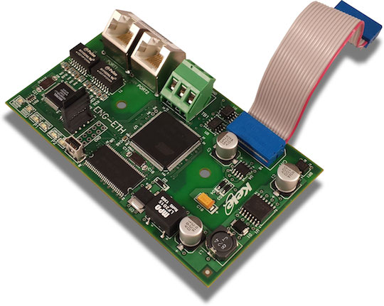
Update!! The ENG-ETH Ethernet Communication Module for endicator is now available. It reads data from the endicator™ main processor, formats the data, and transmits it over Ethernet using BACnet IP, Ethernet IP, and Modbus TCP protocols. The module also hosts a website where meter status can be viewed using any browser that supports Adobe Flash.


For 30 years Kele has been the building automation industry distribution leader, providing parts, solutions, and world class personal customer service. Kele works hard to stay ahead of the curve when it comes to industry changes while always focusing on maintaining the highest level of customer service.  Our power monitoring offering is no exception. Kele has been offering a wide variety of power monitoring brands and products since 1983 and building power monitors since 1993.

Power monitoring is not new to the building automation and energy management industries. Those that have been around building automation and energy management systems can, almost jokingly, say “We were green before green was a thing.” However power monitoring has changed. With the growing focus on saving energy and resource management, power monitoring has been thrust to the forefront of building automation and energy management.  Enter endicator™. Kele’s new power monitor.


Kele’s endicator™ power monitor, introduced earlier this year, is the cutting edge of power monitoring devices. Designed with future upgradability in mind, the endicator™ power monitor gives user the ability to make changes and perform upgrades in the field. Firmware, communication capabilities, and other features can be upgraded according to changes in your customer’s needs. This kind of forward thinking sets endicator™ apart from the others. Think of it as “future proof”.

Here are just a few of the many features of the endicator™ power monitor:

  • NEMA 4 enclosure standard
  • KWH Accuracy class 0.5% ANSI C12.20 For meter alone with unmatched CTs.
  • 0.5% system accuracy with factory calibrated matched CTs.
  • Data port for setup and trend retrieval
  • Measure voltages up to 32,000 VAC (voltages over 600 VAC require the use of a potential transformer, not included)
  • Supports 0.333V safe CTs and 5A CTs (must use optional 5A adapter board)
  • BACnet MSTP, LonWorks, N2 and Modbus RTU available
  • Password protected configuration
  • Powered by separate 24 VAC supply
  • On-board data logging
  • Auto configuration
  • Upgradable firmware through data port
  • Bidirectional power measurement
  • CSI (California Solar Initiative) approved

Kele doesn’t stop there. We also offer power monitoring units from Honeywell, Veris, and WattNode.

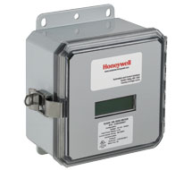
Honeywell H-Series The Honeywell H-Series 500 submeters, available from Kele, feature a direct-read 8-diget LCD display of cumulative kWh. The H-Series 500 also is UL Listed and meets or exceeds ANSI C12 national accuracy standards. Communication options include Modbus RTU or TCP/IP, BACnet IP or MSTP, and LonWorks.
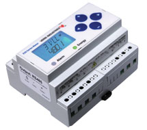
Veris’ E50 Series power meters, also available from Kele, provide a solution for measuring energy data with a single device. The E50 series is conveniently mounted on DIN rail, has password protection capability, and works with popular 0 to .333V or 0 to 1V current transformers. Veris E50
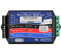
 WattNode The WattNode NC series AC power meters can communicate over 50 values via BACnet and over 27 values via LonWorks. WNC series meters have diagnostic LEDs that provide per-phase indication of power to help with installation and troubleshooting.

These are just a few of the many power monitoring devices that are available from Kele. We also have current transformers, current transducers, voltage potential transformers, and more – all with Kele Inventory, Kele Service, and Kele Technical Support. Check out our complete power monitoring line at Kele – Your Source For power monitoring.