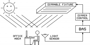
 A very popular way to decrease energy usage these days is to use dimmable lighting fixtures and throttle back on the electrical lighting when outdoor light is available through windows or skylights. A light sensor such as the Kele MK7 family can feed light level information into a building automation system (BAS). The BAS can then use an intelligent algorithm to vary the electrical lighting level with changing outdoor light levels to maintain a constant level of indoor illumination while saving energy.
In order for the BAS to command the dimmable lighting fixtures to the desired light level, some sort of control interface must exist between the BAS and the light fixtures. There are several types of light dimming systems out there in the world with different control interfaces. The one we want to discuss today is known as the “0-10V current sinking” dimming system. We will also briefly mention several other types of light dimming systems, but they are not the focus of today’s article.
Classic Phase-Chopped High Voltage Light Dimmer System
The first light dimming system we’ll briefly touch on is the classic phase-chopping system. These dimmers connect in series with the high-voltage line to the lighting load and perform the dimming by removing part of each half-wave of the AC cycle:
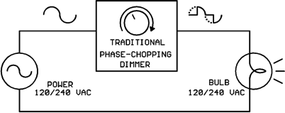
This dimming system is typically limited to small-to-medium incandescent loads although some of the newer CFL and LED light bulbs will work with it also. These dimmers are typically manual-adjust units without any control interface to a BAS.
Networked Digital Light Dimming Systems
DMX is a networked digital light dimming/control system used in theaters and at rock concerts. DALI is a networked digital light dimming/control system that is popular in Europe and has found some use in the USA.
“0-10V Current-Sinking” Light Dimming System
This is the dimming system we want to discuss today. It is formally defined in the standard IEC 60929 Annex E.
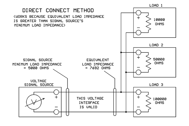
Although the interface is named “0-10V” it’s not like the 0-10V analog interfaces we are accustomed to in the HVAC world! In the HVAC world the 0-10V is generated in the controller and is consumed by the load like this:
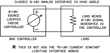
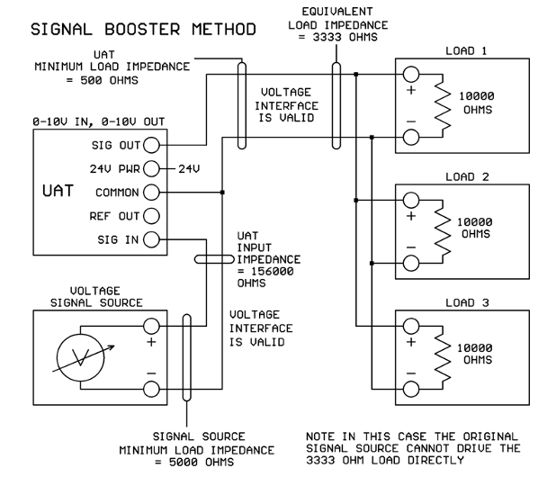
The classic 0-10V analog interface shown above is NOT the same as the 0-10V dimmable lighting interface! The “0-10V Current Sinking” lighting interface is implemented as shown in the following diagram:
Wow, that’s quite a bit different than what we are used to! The voltage source for the 0-10V signal is actually contained in the lighting fixture, not in the controller!
The voltage source is typically more than 10V, something in the 11-20V range. A series resistor located inside the lighting fixture allows the light dimmer module to “pull down” the original voltage to the desired value. The dimmer module does this by varying its own internal resistance until the desired voltage appears across its output terminals. Those of you who have studied circuit theory will recognize the combination of light fixture resistance and dimmer module resistance as a classic “voltage divider” circuit.
You will notice that a small current flows around the loop from light fixture to dimmer module and back to the fixture. The value of this small current is NOT the control signal, the voltage across the terminals is the control signal. The small loop current is just a necessary evil to make the voltage divider circuit work as needed.
Hmmm… I’m getting the idea that a standard 0-10V output from a BAS controller may NOT work with a 0-10V dimmable lighting fixture. Is that correct?
That is correct. Your 0-10V BAS output might work with a dimmable lighting fixture if you are very lucky. But probably, it won’t work. If you’re unlucky, you might burn up the 0-10V output on your BAS controller.
So… I need a specialized dimmer control to drive these 0-10V lighting fixtures. Where can I get such a dimmer control?
We’re glad you asked. J Kele sells the LDIM2 light dimmer module which is specifically designed to interface with 0-10V current-sinking dimmable lighting fixtures. The LDIM2 can accept standard 0-10V or 2-10V or pulse-width input signals from your BAS controller and provide the necessary current-sinking 0-10V output for the light fixtures. The 0-10V current-sinking output to the light fixtures is electrically isolated from the BAS signal inputs to prevent any interference between the two systems.
Can one LDIM2 dimmer module control multiple lighting fixtures?
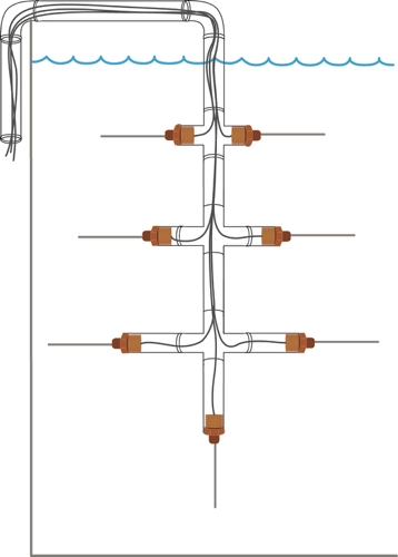
Yes it can, just wire up the wire pairs from multiple lighting fixtures in parallel like this:
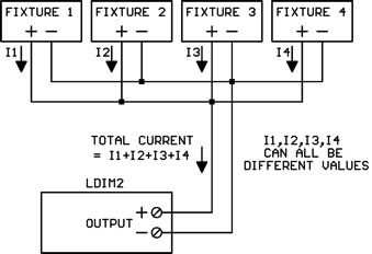
The total current flow through the LDIM2 output will be the sum of all the individual lighting fixture currents. Different makes and models of fixtures may supply different current values.
How many lighting fixtures can I attach to the LDIM2 output?
That depends on the control current flow from each lighting fixture. The maximum load current allowed on the LDIM2 output is 0.5 amps. So you can add lighting fixtures until the total from all the fixtures reaches 0.5 amps, but you can’t go further. If, for example, each fixture supplied 1 mA of current, you could attach 500 fixtures to one LDIM2 (0.5 amps / 0.001 amps = 500).
If you have so many lighting fixtures that the total control current exceeds 0.5 amps, wire them up in “banks” where each bank is 0.5 amps or less and is controlled by its own LDIM2 dimmer.
How do I find out how much current a particular model lighting fixture puts through the LDIM2?
The IEC 60929 Annex E standard specifies that the control current value should be between 10 uA (microamps) and 2 mA (milliamps). However, there’s absolutely no guarantee that the lighting fixture manufacturer adhered to these guidelines.
If you’re really lucky, maybe the lighting fixture data sheet will tell you the value of the control current. If you cannot find a published value for the control current, please don’t just assume a value. Also don’t mistake the lighting fixture’s supply current for the fixture’s control current. The fixture’s supply current will almost always be on the data sheet, but will be a much higher value, possibly several amps.
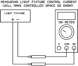
If you have access to the physical light fixture(s), you can measure the control current with your DC mA meter. Just put it across the two signal wires coming down from the fixture(s). But beware, the mA meter resistance is less than 1 ohm. It will pull the voltage down very close to zero volts, and the lights will go dark, so don’t do this during work hours on an occupied space unless the people are warned first!
What happens if the fixture wires are connected to the LDIM2 with the polarity reversed?
If the lighting fixture wire polarity is hooked up backwards, the voltage will go to about 0.7V which is near 0% light level. Nothing will be damaged, but the lights will go out.
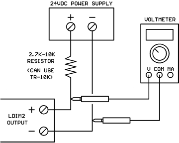
How can I test the LDIM2 on my workbench if I don’t have a dimmable lighting fixture available?
You can use a standard 24VDC supply and a pull-up resistor like this:
The catalog description of the LDIM2 is “fluorescent dimming control.” Will it work with dimmable LED lighting fixtures?
Yes, it will work with any dimmable lighting fixture that uses the 0-10V current-sinking interface. You just need to figure out what control current the fixture puts through the LDIM2’s output so you don’t overload it by attaching too many fixtures.
Conclusions
The 0-10V current-sinking interface used by dimmable lighting fixtures is not compatible with the standard 0-10V outputs used in HVAC/BAS systems. You should use a specially-designed dimmer control module such as Kele’s LDIM2 for dimmable lighting fixture applications.
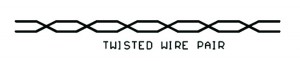
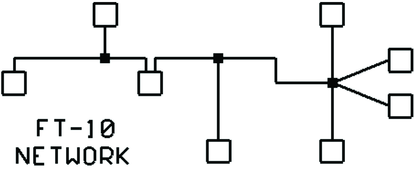
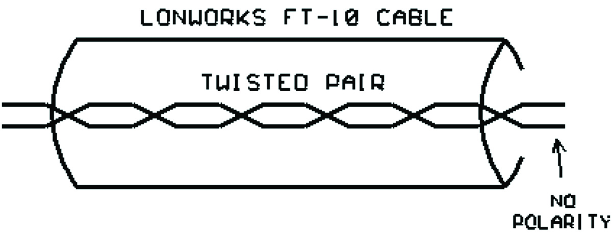 The FT-10 twisted pair has no polarity – the wires can be attached to each Lonworks device without worrying about which wire is “+” and which is “-“.