If you live in the world of HVAC design/installation, sooner or later you’re going to need to take measurements on a circuit using a voltmeter (even if it’s “not your job,” we all know how that goes).
So we thought it would be a good idea to put together some basic instructions on using a voltmeter. Even if you’ve been using a voltmeter for years, there might be some tidbit of information here that you hadn’t thought about before. 🙂
Voltmeter or Multimeter?
These days you’d be hard-pressed to find a test meter that just measured Volts and nothing else. Everyone manufactures multimeters that measure volts, current, resistance, and possibly other things too (frequency, capacitance, temperature with accessory probe, etc.). But today we’re just going to concentrate on making voltage measurements with our multimeter.
Plug the Meter Leads Into the Correct Meter Jacks
This seems obvious, but this author has failed to do this many times. Shown below is a typical multimeter face layout. This is an actual meter Kele uses in training classes. It’s a few years old but the functionality of the controls is the same as a modern multimeter. Note that your multimeter controls may be arranged somewhat differently or completely differently. No one likes to do it, but you might want to actually read your multimeter instruction manual if it hasn’t been thrown away/lost by now!
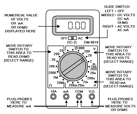
To read voltage, plug the black meter lead into the COM jack and plug the red meter lead into the V/ohm jack.
Do not mistakenly leave the red meter probe in the mA or Amps jack and try to measure voltages between two points in a circuit. In the mA or Amps mode the meter leads essentially look like a direct connection and you will be shorting out the two measurement points in the circuit. Bad things can happen. Since we are discussing voltage measurements today, that’s all we’re going to say on the subject. You have been warned.
Set the Meter Selector to Volts
The meter selector switch has different major areas for choosing whether you want to read voltage, current, resistance (ohms), or possibly other things. You need to move the selector switch to one of the positions in the Volts area (upper right area on our example meter).
Set Meter Range (Unless You Have an Auto-Ranging Meter)
Our example meter has different voltage ranges to choose from based on the maximum voltage you expect to measure. Always choose the smallest range that’s higher than the highest voltage you are expecting to measure. For example, if you are going to measure 24V then on our meter you would select the 200V range (because the 24V we want to check is higher than the next lower range which is 20V).
If you accidentally select a lower range than the voltage you are trying to measure, the meter won’t be damaged, you’ll get some kind of “over range” indication on the display. This can vary from meter to meter. Sometimes it’s a row of horizontal dashes, sometimes it’s “OL” for overload, or maybe something completely different.
The only way you should damage your voltmeter from overvoltage would be if you exceed the maximum rating for the meter. That value should be in the instruction manual and it’s almost always printed on the meter face too. It’s pretty high, typically something like 750V or 1000V, values you will probably never encounter in HVAC work.
If your meter has an Auto-Ranging function you don’t have to worry about setting the range, the meter will figure it out for you. It usually starts on the most sensitive range and, if it sees an over-range condition, moves to the next higher range, etc. until it finds the most sensitive range that does not result in an over-range condition.
Auto-ranging is very handy. The downside is that it can take the meter longer to display a final stable voltage reading because it has to trial and error each time to find the right range. A fixed-range meter manually set to the correct range will stabilize to a usable reading faster since it doesn’t have to experiment to find the correct range.
Set Meter for AC or DC Volts As Needed
If you set the meter to read DC volts and put the probes on an AC voltage source, the meter will read essentially zero volts (the readout might jump around the zero reading a bit).
If you set the meter to read AC volts and put the probes on a DC voltage source, the meter display will jump up momentarily and then “coast” back down to essentially zero volts over time.
So be careful – an incorrectly set meter will make you think there is no voltage present when there really is.
If you are probing a “mystery circuit” and you’re not sure whether the voltage between two points is AC or DC, you can try both settings on the meter to see which gives you a non-zero value.
Place the Meter Probes on the Circuit Points To Be Measured
To make a voltage measurement, you do not need to disconnect anything in the circuit. You do that for current or resistance measurements (which we are not covering today).
Remember to keep your fingers on the insulated probe handles, don’t touch the metal probe tips with your fingers. You might know the voltage is supposed to be low (24V) but why take a chance in case you’re mistaken or there’s a short in the wiring?
In the case of AC voltage, there is no polarity to worry about, the signal will always read positive on the display no matter which way the probes are placed.
In the case of DC voltage, the red probe should go on the more positive point and the black probe should go on the more negative point. But if you should get it backward no harm is done, the meter will just display a negative voltage value, the magnitude of the reading will still be correct and you will know that the point with the black probe is actually the more positive point.
If the display shows an over-range condition, just move the meter voltage selector to the next higher range and try again.
Average-Reading Versus True-RMS AC voltmeters
Not all voltmeters are created equal when it comes to measuring AC volts. There are two different measurement techniques in use.
“Average-Reading” AC voltmeters only give a correct reading if the AC voltage is a sine wave. Most AC voltage signals we read in the HVAC world are sine waves (or very close) so this is typically acceptable. Less expensive meters tend to use the average-reading measurement technique.
“True-RMS” AC voltmeters will give a correct reading no matter what wave shape (does not have to be a sine wave). This technique is typically reserved for the more expensive meters.
Do Newbie Practice On Low Voltages
If you’re new to taking voltage measurements with a voltmeter, we recommend you start with a low-voltage source just to keep things really safe. A step-down transformer with a 24VAC secondary or a bench power supply with a low voltage DC output would be great.
Follow the recommendations above and taking voltage measurements with a multimeter should be second nature in no time at all!


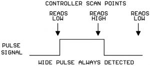
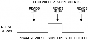
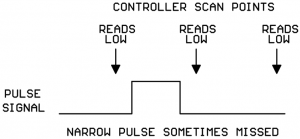
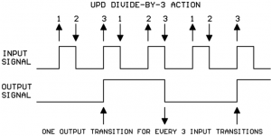
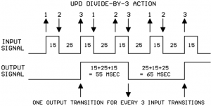
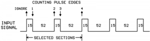
 So we see that the output pulse duration will need to be a minimum of two high portions and two low portions of the input signal.