With schools out for the year in most parts of the country as a measure to prevent the pandemic spread—and soon everywhere for summer break, retrofitting and maintenance work on HVAC systems are on schedule to happen soon if they are not already underway. Among other needs, schools retrofit in order to reduce energy consumption, minimize noise pollution, and upgrade air filtration systems to maximize student and faculty health. And with each retrofit, contractors are tasked with following multiple standards and requirements to ensure the health and safety of all who enter the facility.
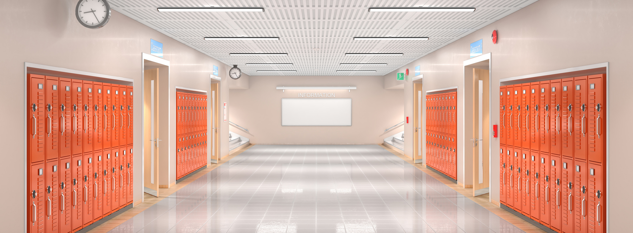
ASHRAE standard 62.1-1999, for example, recommends that each person in a classroom receive 15 cu. ft. per minute (cfm) of fresh air and a classroom with 30 people requires a ventilation rate of about 450 cfm. Once you’ve factored in how a school or university is constructed, it is easy to see why HVAC systems present a unique challenge in meeting standards. There are also zone requirements that must be kept up to standard as well.
For most retrofits, there are two generalized groups that are addressed: centralized and decentralized systems. Each system operates and controls specific zones within the facility. Centralized systems include air handling units, chillers, applied rooftop systems, and indoor vertical self-contained systems. Decentralized systems include outdoor air ventilation systems, water-source heat pumps, fan coils, and unit ventilators.
In order to stay under budget and on schedule, easy access to parts is a must. That’s where Kele comes in. We know that with so many systems to retrofit within just one facility, finding parts that meet your budget can be tough. Our technical service team also understand different standards in place and can make product recommendations accordingly. With our 1.8 million in-stock parts from over 300 suppliers, we’ve got you covered. Visit kele.com today and let us give you the project support you need.
Read more about school projects here.