Every decent-sized Building Automation contractor should have a sensor whisperer; the guy who knows instinctively exactly where each sensor should go…even when there’s no plan. If your company doesn’t have a sensor whisperer, we can help. Our technical support staff can always help you with just the right touch for perfect sensor installation guidance.
But for the rest of us sensor newbies, we offer these 6 obvious and not-so obvious tips for spotting and installing wall-mount temperature or humidity sensors:
- The most obvious factor of all is to confirm that the sensor location is in the space served by the air handler (or other terminal unit) with which it is associated. If the ceiling is in place, it’s best to at least have a chat with the folks who installed the sheet metal – make sure nobody decided to do some re-zoning without informing you.
- Treat sensors like vampires, avoid sunlight. In fact, it’s better to stay at least several feet away from any portion of wall that gets direct sunlight. Surface temperatures of sunlit walls can be as much as 20°F (11°C) higher than room air, and this heat can be conducted to a nearby sensor.
- Avoid outside walls, unless the only other choice involves direct sunshine.
- Avoid other sources of heat within the space. If not yet occupied, ask where electrical equipment will be placed. A temperature sensor on a wall above a copy machine can make a room mighty cold. If sensing humidity, an elevated temperature at the sensor location will cause it to report lower values than a sensor at actual room temperature.
- Avoid the supply air stream. Sometimes this can be a challenge. Even if the room’s supply air diffuser is a good distance away from the wall, its output may travel across the ceiling and down the wall, causing false readings at the sensor. If a diffuser cannot be avoided, line up the sensor with the corners of diffusers. If all else fails it might be time to get creative. We’ve seen cases in which shelves had to be built to shield a sensor from direct blasts of supply air.
- Avoid leaks. Even in interior rooms, the air from the space within the wall can be warmer or cooler than the conditioned area. In some cases, the moisture content can be very different, too. Seal the holes, including the hole for the sensor cable.
These 6 tips are what all sensor whispers know instinctively, for the rest of us, there’s Kele. We can help with your sensor installation. Remember, at Kele we have more than 100 combined years of technical expertise in Building Automation and some of us might even have…the gift.
 One of the great perks of working for the nation’s leading supplier of building automation products is field trips to locations where there are interesting applications for our products.
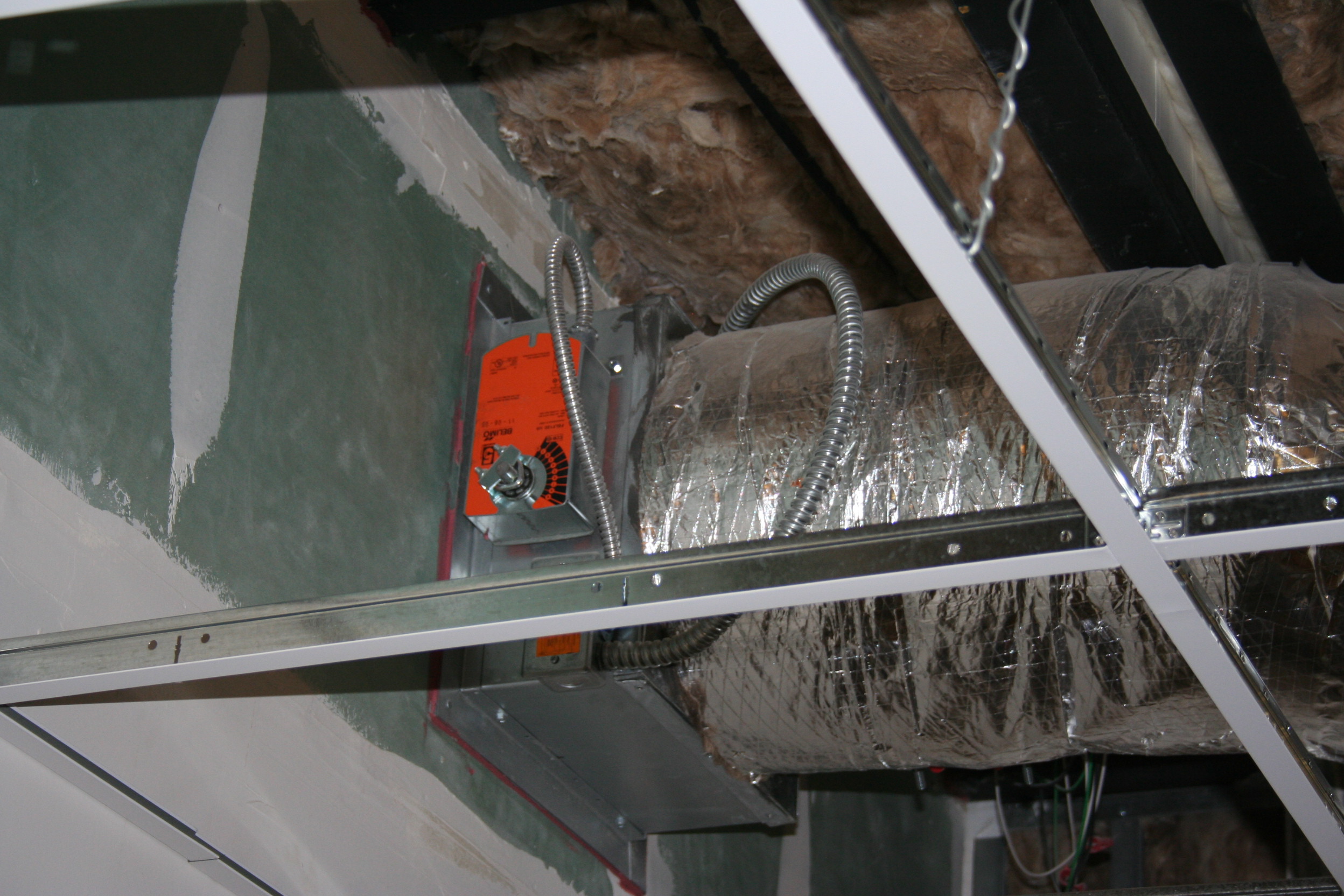 Belimo Actuator
 Setra Room Pressure
 Beginnings of a Modular Hospital
 Module Being Lifted into Place
 All Modules in Place
 View from the Top
 Well, when it comes to intriguing new applications for Kele’s peripherals in building automation systems, I just can’t help being nosey.
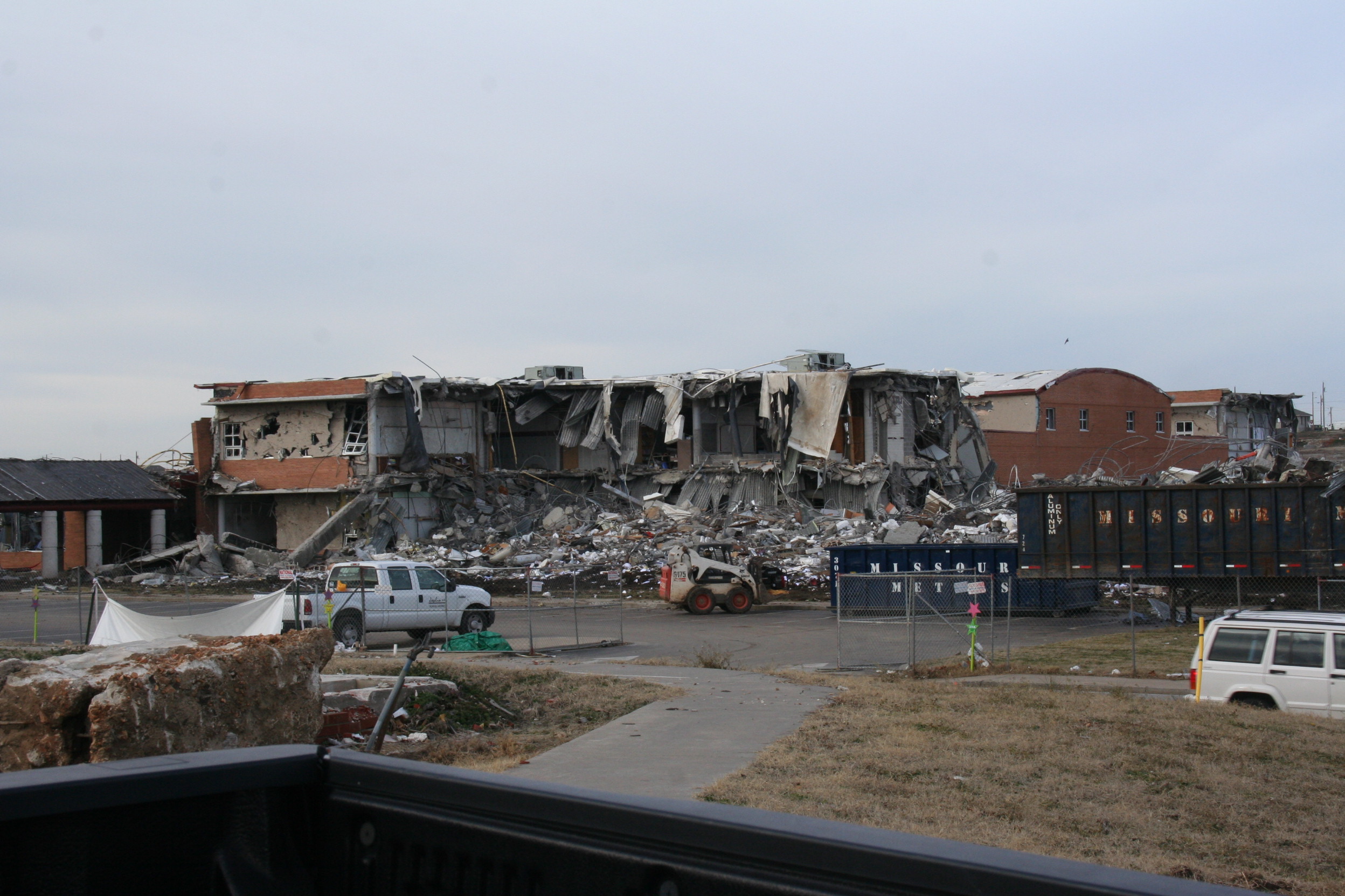 High School
 Now a Vacant Lot